External interference situations can severely impact the performance of a mobile network, impacting the subscribers’ experience. Because of this, mobile network operators should find mechanisms to mitigate this issues effectively and quickly. In this article we present a general description of the most common types of external interference in mobile networks, what is the typical process to find it and how can operators leverage the CellSpectrum solution to accelerate this process.
In the context of a mobile network, what is external interference?
In every mobile network there is interference. All 5G/LTE/UMTS networks use a frequency reuse of one, this means that all UEs and base stations transmit over the same bandwidth, causing “internal interference”.
The system is designed to tolerate and handle this internal interference, and only in severe scenarios (very high traffic, cell overlapping or pilot pollution) we will observe significant degradation of user experience. Internal interference issues can be detected by analyzing the network’s performance, traces or Drive Tests.
The scenario changes when the interference doesn’t come from the mobile network or its user, but from external sources. In that case, the network’s self-regulation capabilities are diminished.
Hereinafter, when we speak of external interference, or simply interference, we are referring to situations in which the presence of unwanted RF energy degrades the normal operation of a wireless communication system.
In downlink, on the other hand, 5G/LTE/UMTS/GSM cells transmit at a higher power than typical interference sources, making it less likely to observe a negative impact in this direction.
External interference impact
The effects of external interference usually vary depending on the interferer characteristics and the affected system.

Given the adaptive nature of modern cellular technologies, the presence of interference may cause the system to use more robust modulation schemes with lower bit rate (for instance, QPSK). In this case, the user perceives a data rate decrease in either uplink or downlink. More severe cases cause more evident problems, such as dropped calls, access failures, bad voice quality, data transmission interruption or high latency.
On the network’s side, the presence of interference causes a decrease in the available air interface capacity. This is due to the increase in usage of resources (PRB, Power, Codes) needed to overcome the interference and maintain an acceptable BLER. Evidently, this affects the end user experience.
Both situations are undesirable for mobile network operators. This is why a fast and effective mitigation methodology is needed, with the objective of minimizing impact time.
Most common external interference sources in mobile networks
External interference sources may vary according to the region or frequency band. Below some of the most common types:
Harmonics and intermodulation products
Harmonics are a normal product of almost all RF transmitters. A harmonic is simply a copy of the original signal that appears at N multiple times of the original frequency. Intermodulation Products are created when two or more signals of different frequencies (including their harmonics) are combined in a non-linear way.
Intermodulation products can be generated at considerable distances from the source frequency. It is common to see this effect when you have multiple transmitters sharing antennas or feeders, or in cases where contaminated, corroded or bad surfaces cause passive intermodulation (PIM)
Equipment transmitting in not allowed bands.
On occasion, service providers may have equipment transmitting on unauthorized bands. For example, radio stations or microwave links.
Another common case is interference at the borders between countries.
Spurious emissions from electronic devices.
Almost all electronic devices emit RF energy at different frequencies. When these signals, or their harmonics, are of sufficient amplitude and fall within the cellular band, they cause interference. Examples: Amplifiers, lamps, screens (neon), industrial equipment.
“Other region” electronic devices
Devices that operate in bands allowed in one region that interfere with bands in others. Examples: Radios, microphones, cordless phones.
Repeaters with improperly adjusted gain.
Private entities can install repeater antennas to improve coverage in a certain band. If these items are set with excessive gain, they may cause interference.
Intentional interference.
It is common for some private individuals or government entities to use jammer devices to limit mobile communications in an area.
External interference “hunting” procedure.
It is necessary go through an elimination process before concluding that we are in presence of an external interference signal.
Some internal causes that may cause a rise in uplink RSSI are:
- Abnormal traffic increase.
- Logical parameters incorrect settings.
- Network interventions.
- Repeaters on service.
Once the operator’s RF team has determined with a certain degree of certainty that external interference exists, the following steps should be taken:
Step 1: Characterize the interference
Before going out to take measurements, the operator should have a clear idea of the interferer signal characteristics.
Intensity: The OSS statistics allow us to obtain an average value of the RSSI that the cell receives on the uplink (RTWP). This value gives us an indication of the level of interference existing in the system.
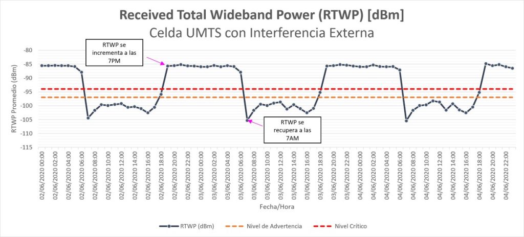
Time variation: Determine if the interference occurs constantly, at certain times of the day, or intermittently. Depending on the timing of the signal, possible points of origin can be determined. For example: if we have an interference that occurs between 7:00 PM and 7:00 AM (see example in the figure below), it is likely related to a lighting system.
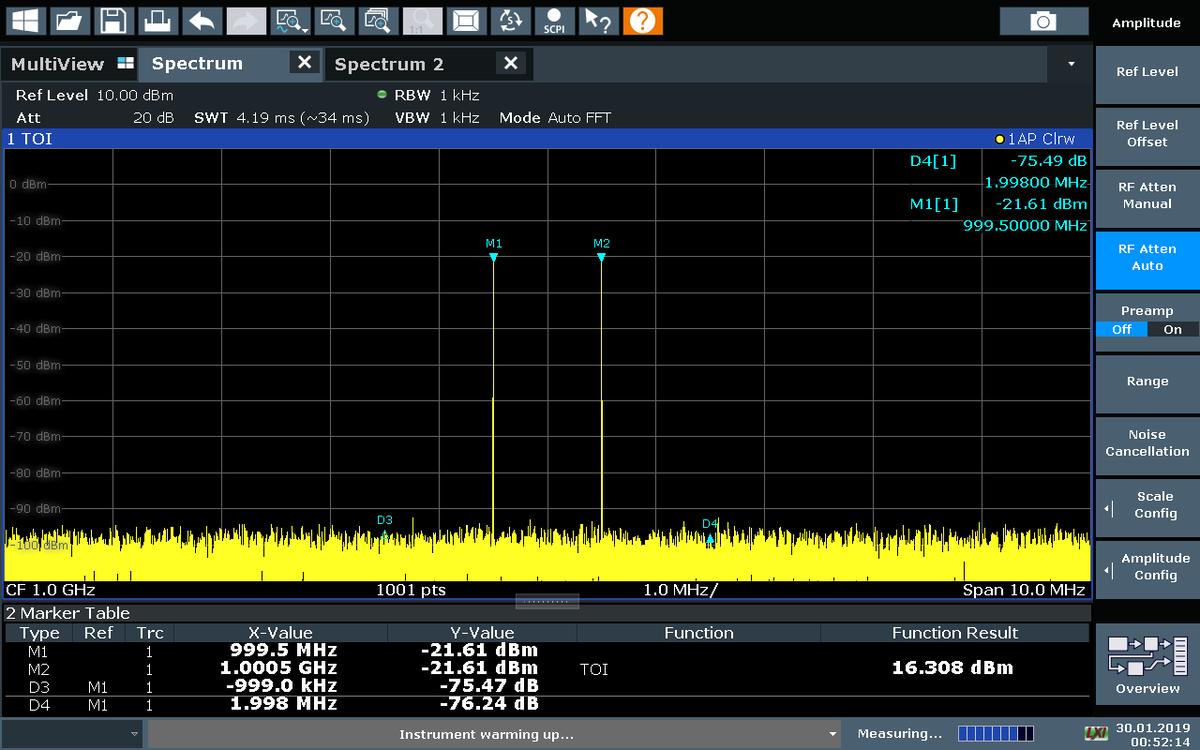
Bandwidth and frequency characteristics: Some equipment vendors offer in their maintenance terminal interface the possibility of monitoring the spectrum from the base station. With this tool, the operator can identify the characteristics of the interfering signal in terms of its bandwidth and intensity.
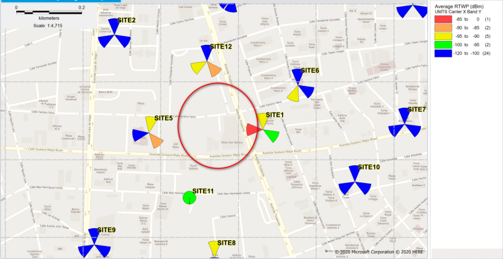
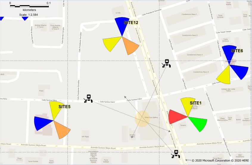
Sites affected: It is good practice to prepare a map that clearly shows which sectors of the mobile network are most affected. As we can see in the image, when viewing the noise levels on the map we can deduce that the possible interfering signal is located in the area enclosed in red.
Step 2: Determine the general location of the external interference
Once the data has been collected in step 1, the operator has enough information to go out and take measurements in the field to find the interfering signal.
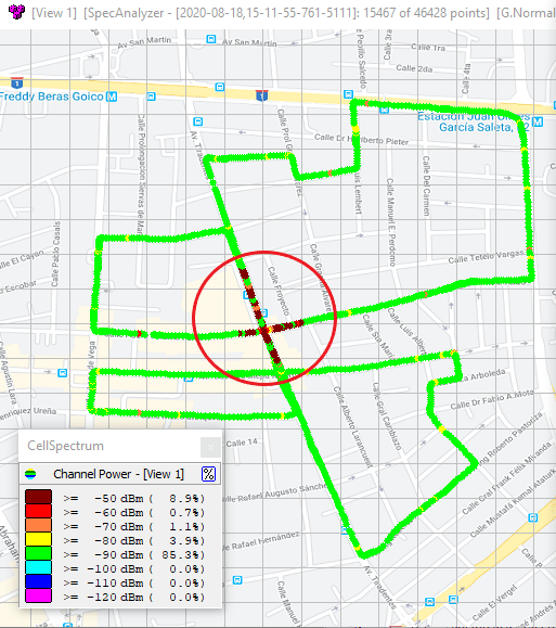
The objective in this stage is to identify the signal in a range of 100 to 200 meters. For this, it is advisable to perform a Drive Test in the affected area using a receiver (such as CellDigitizer) and an omnidirectional antenna. The objective of this drive test is to generate a heat map where the specific areas where the RSSI increases abnormally are identified.
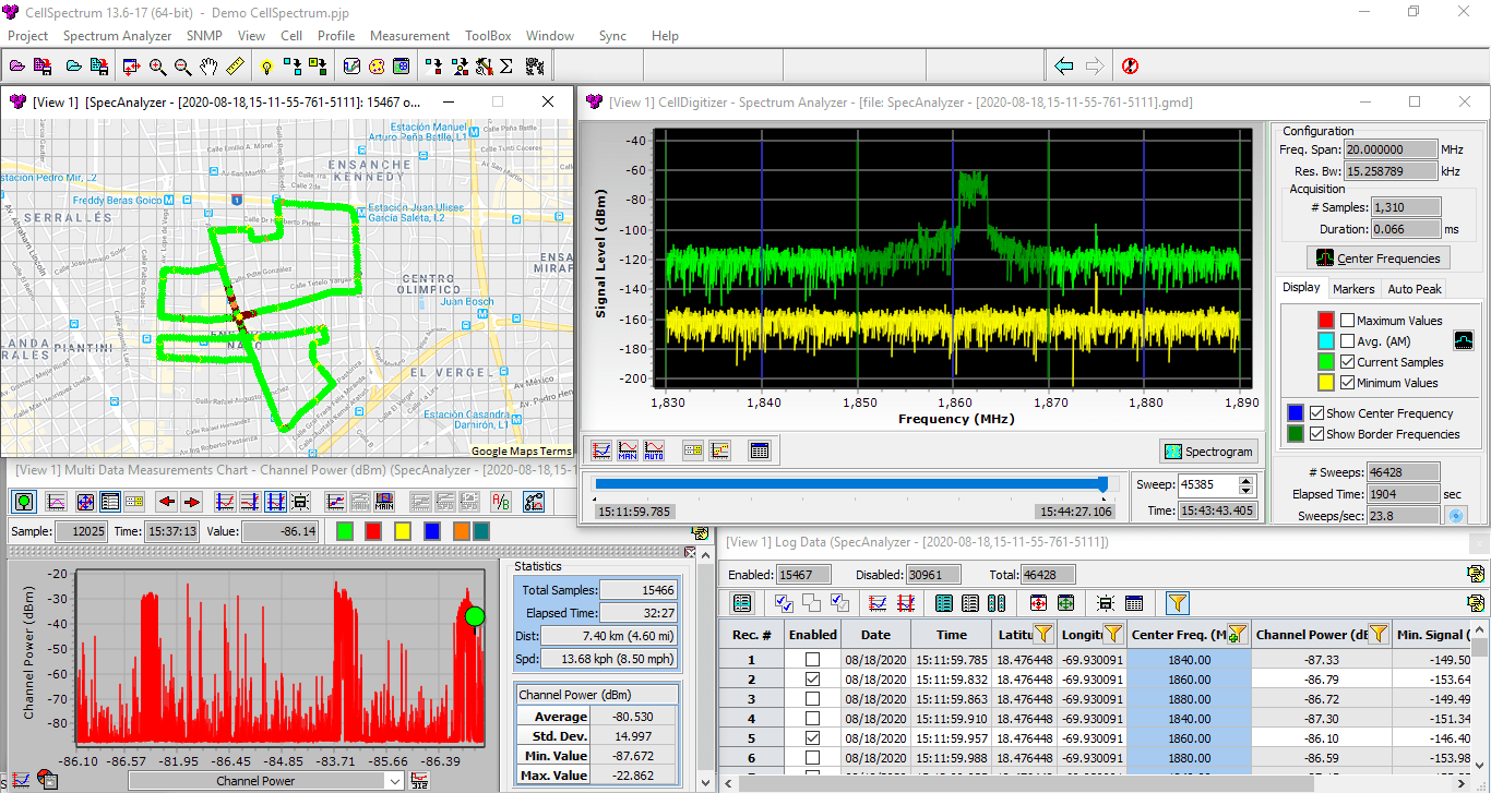
In the figure we can see a map of a Drive Test carried out with CellSpectrum, one of the components of Celplan’s CellWireless solution. This plot allows you to narrow the search radius of the interference.
Step 3: Determine the specific location of the external interference
Once the operator has narrowed the search area to a space of around 200 meters or less, the next step is to take measurements “on foot” with a spectrum analyzer and an appropriate directional antenna (for example, a Yagi or Log-periodic antenna).
The field technician performs a scan at different points, recording the location (coordinates) and direction (azimuth) of the interfering signal, until the location of the interfering source is triangulated.
Once the source of the interference has been detected, the operator manages the tests to turn off the interfering signal. At the same time, the operator should verify in the OSS that the interference has stopped and the quality of service recovers.
In our experience, we have seen operators skip step 2 and go straight to 3. This can be counterproductive, as covering more territory takes more time to find interfering signals. In addition, having a more detailed drive test measurement allows a better diagnosis to be made and possible false positives to be ruled out.
If the operator has a solution such as CellSpectrum available, during step 2 they will be able to obtain additional valuable information, which will help with troubleshooting. Let’s look at this in the next section.
How can we rely on CellSpectrum to find external interference sources more easily?
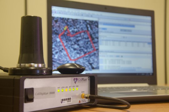
CellSpectrum is Celplan’s spectrum analyzer solution that Ekspresa commercializes in Mexico, Central America and the Caribbean. It allows you to scan the spectrum captured by the CellDigitizer hardware.
Among its main functionalities we find:
- It supports a wide range of frequencies: 0.1MHz to 40GHz.
- Allows you to record and replay measurements.
- All measurements are georeferenced, which facilitates data analysis in the office.
- High dynamic range and protection against saturation via automatic gain control.
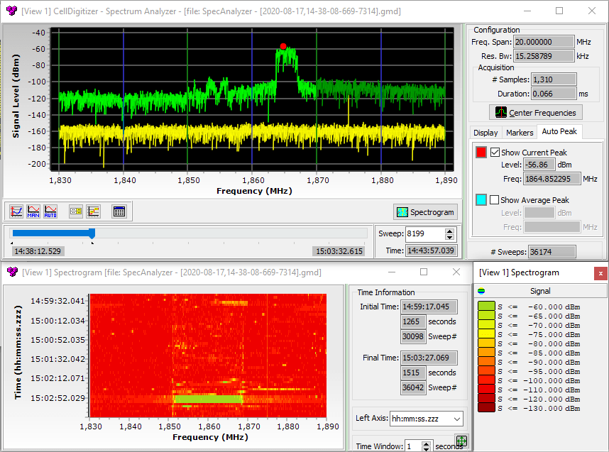
- Includes spectrogram display, allowing to identify signals that vary over time.
- Cost effective solution, compared to competitors.
With CellSpectrum an operator can perform a Drive Test in an area of interest to generate a heat map showing the interference conditions.
Later, in the office, the RF engineer can analyze in detail the characteristics of the spectrum at different points along the path and draw conclusions regarding the attributes of an interference potential.
Using the spectrogram view, it is easy to identify if an interference varies over time:
With CellSpectrum, operators have a flexible and powerful tool that allows them to easily analyze the radio environment and detect sources of interference efficiently and quickly.
Conclusions
Identifying external interferences is a complex topic. In this article we wanted to capture the most important general notions on this topic. In summary:
- There are many types of sources of interference that affect mobile networks.
- Interference negatively impacts the user experience.
- Operators should have methodologies and tools that allow minimizing the time for detecting interfering signals.